


Helical Gear Motor vs Worm Gear Motor: Which Is Better
 Oct 30, 2026|
 View:6
Neither the helical gear motor nor the worm gear motor wins everywhere. Your application requirements decide which one works best for you. A helical gear motor may suit one project, while a worm unit fits another just as well.
Several factors separate these two drives. You should weigh efficiency, torque and load capacity, speed reduction, heat, self-locking behavior, footprint, maintenance, and total cost of ownership. Each factor shifts the answer for your duty cycle and load profile.
This guide gives engineers and OEM buyers a clear, practical comparison. You will see how each design performs and which applications favor it. Use the evidence here to make a confident, application-based selection.
Key Takeaways
Helical gear motors save energy with high efficiency, making them ideal for continuous use.
Worm gear motors cost less upfront and fit tight spaces with their right-angle design.
Choose helical for heavy loads and long hours; choose worm for intermittent duty and self-locking.
Worm gears often hold loads without a brake, but always verify safety for critical applications.
Consider total cost over time: energy savings can outweigh a higher purchase price.
Quick Comparison at a Glance
Comparison Table
The table below puts the two designs side by side across the factors that decide most selections. Treat each row as a starting point, then confirm the numbers against the specific catalog data for your candidate unit.
Factor | Helical Gear Motor | Worm Gear Motor |
|---|---|---|
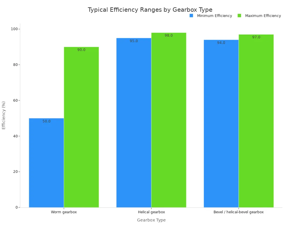
Efficiency | Typically 90–97% or more; rolling contact keeps losses low | Roughly 50–90%; falls as ratio climbs and load rises |
Gear ratio range | 1:1 to 10:1 per stage; multi-stage units reach far higher total ratios | 5:1 to 75:1 in a single stage; some families extend to 100:1 |
Torque | High torque capacity for heavy, long-term loads | Suited to moderate torque at low output speeds |
Heat generation | Low; efficient rolling contact wastes little energy as heat | Higher; sliding contact raises thermal load |
Self-locking | Generally backdrives; a brake holds the load | Many configurations self-lock and hold loads without a brake |
Footprint | Inline, parallel shaft layout; longer axial length | Right-angle layout; saves space in compact installations |
Maintenance | Long service intervals; durable gear life | Lubrication matters more; the worm wheel wears over time |
Upfront cost | Higher purchase price | Up to 40% cheaper upfront |
Total cost of ownership | Lower energy use offsets the higher price in continuous duty | Lower initial spend; energy and wear costs grow with running hours |
Reading the Table for Your Application
Start with your duty cycle. A helical gear motor shines in continuous operation, because its efficiency stays high across long running hours. Every point of efficiency you keep turns into energy savings on the utility bill. Worm units trade some of that efficiency for compactness and a lower upfront price, so they fit intermittent duty well.
Next, check your load profile. Heavy, steady loads with high torque demand favor the helical design. Low-speed output with modest torque leaves room for a worm unit, especially where a right-angle layout solves a space problem.
Then look at holding requirements. If the load must stay put when the motor stops, a self-locking worm configuration can remove the brake from your bill of materials. If the load backdrives freely, plan for a brake on a helical drive.
Finally, weigh the cost rows together. A worm gearbox can cost up to 40% less at purchase. That gap shrinks over years of continuous running, when energy losses and wheel wear add up. Match the row that dominates your operating hours, and the choice usually becomes clear.
What Is a Helical Gear Motor?
Design and Characteristics
A helical gear motor pairs an electric motor with a gearbox whose teeth are cut at an angle to the shaft axis. That helix angle typically falls between 10° and 45°. The angled teeth create rolling contact rather than sliding contact, so power flows through the mesh with very little friction. The gearbox sits inline with the motor, which gives you a parallel shaft layout.
The angled tooth geometry changes how the gears behave under load. Each tooth starts its contact before the previous tooth disengages, so several teeth share the load at any instant. This progressive engagement produces smooth, quiet running. It also raises the contact ratio above what a spur gear can reach, which spreads contact stress more evenly and supports heavier loads. A well-designed helical stage reaches power transmission efficiency of 96–98%.
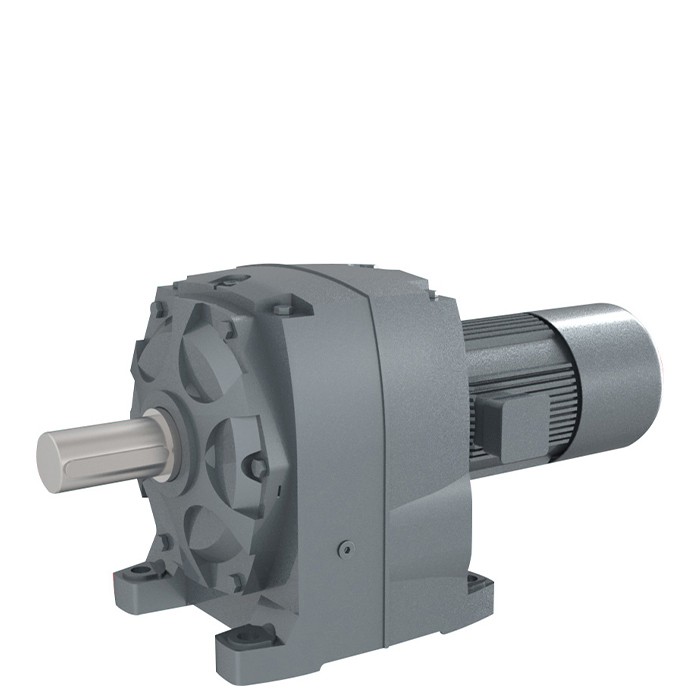
The GNORD S4 Gear Motor shows how these traits translate into a real product. It comes in 12 sizes with torque from 85 to 25,000 Nm, ratios from 2.8 to 10,000, and power from 0.12 to 90 kW. The monoblock design keeps the gearbox and motor aligned as one unit. You can order foot or flange mounting, and the unit is built to DIN and AGMA standards.
Strengths of Helical Drives
The helical design delivers four practical strengths:
Inclined teeth engage and disengage gradually, so power transmits smoothly and continuously.
Stable meshing keeps operating noise low.
The higher contact ratio supports greater load capacity.
Stable meshing suits continuous-duty operation.
These strengths make the S4 a fit for demanding duty cycles. You will find helical gear motors at work in new energy equipment, plastic and rubber processing, lifting and transportation systems, chemical mixing, power supply installations, and grain and oil machinery. In each case, the smooth mesh and high efficiency pay off over long running hours.
What Is a Worm Gear Motor?
Design and Characteristics
A worm gear motor pairs an electric motor with a gearbox built around two parts: a worm screw and a worm wheel. The worm is a spiral-threaded shaft. It drives the wheel, which is a toothed gear set at a right angle to the worm. The shafts cross at 90°, so the output turns perpendicular to the motor. Contact between the two parts is sliding, not rolling.
The thread count sets the reduction. A single-start worm has one continuous thread, and it advances the wheel by exactly one tooth per full revolution. The ratio equals the number of wheel teeth divided by the number of thread starts. A 40-tooth wheel with a single-start worm gives 40:1. The same wheel with a 4-start worm gives 10:1. One worm-and-wheel pair commonly spans 5:1 to 100:1, which delivers high single-stage reduction in a small package.
Designers also pair materials on purpose. A hardened steel worm runs against a softer bronze or polymer wheel. This pairing concentrates wear on the replaceable wheel and lowers friction.
Strengths of Worm Drives
Three traits make worm drives a practical choice. First, the right-angle layout saves space in compact installations. Second, many configurations self-lock below a low lead angle, generally under about 5°, so the load holds without a separate brake. Third, the gearbox carries a lower upfront price than a helical unit.
The design also runs quietly and smoothly, thanks to the sliding mesh. Efficiency sits at a moderate 40–90%, which suits intermittent duty. A multi-start worm trades some reduction per stage for smoother operation, higher efficiency, and reduced friction. Match the thread type to your speed and holding needs, and the worm drive fits well.
Efficiency Comparison
Helical Efficiency Across Loads
Rolling contact sets the helical design apart. Angled teeth roll across each other instead of sliding, so very little input power turns into friction. A single well-built stage reaches 94–98% efficiency, and a helical gear motor typically holds 90–97% or more across its full range. Stack three stages at 98% each and total efficiency lands at 0.98 × 0.98 × 0.98 = 94.1%. Just under 6% of your input power becomes heat.
Load position matters too. Electric motors reach peak efficiency between 75% and 100% of rated load. Size the motor so your normal duty point sits in that band, and the whole drive runs near its best. A three-stage unit chasing an exact ratio often loses more than a two-stage unit with a carefully split ratio. Choose the stage count for efficiency first, then fine-tune the ratio.
Worm Efficiency Limits
Sliding contact costs you power. The worm thread drags across the wheel teeth, and friction converts a large share of input into heat. Efficiency depends heavily on thread count:
Worm gear configuration | Typical efficiency range |
|---|---|
Single-start | 40%–50% (up to 50%–70% under favorable conditions and high machining accuracy) |
Double-start | 70%–78% |
Multi-start | 78%–92% |
Higher ratios push efficiency down further, because each added reduction stage multiplies the losses. Surface stress and thermal load rise at the same time.
Transmission efficiency varies with load magnitude, and usually reaches its optimum under moderate load. Long-term heavy-load and overload operation should be avoided.
Efficiency can even rise slightly under load, but overheating erases that gain once you push past the rated range.
Now tie both designs to your energy bill. Optimized gear ratios cut energy consumption by 15%–25%, and high-efficiency gear systems save $5,000–$50,000 per year in typical industrial settings. Over a decade of continuous duty, that gap easily outweighs a lower purchase price.
Torque and Load Capacity
High-Torque Performance
Helical gearing handles heavy loads well. The angled teeth keep several teeth in contact at once, so the load spreads across a longer contact line. That shared contact lowers stress on each tooth and lets the gear set transmit more torque. A helical gear motor therefore suits heavy-load, long-term operation, where the drive must push hard hour after hour.
Worm gearing follows a different pattern. The single worm thread carries the full load through a sliding mesh, so torque capacity stays moderate. Worm units fit low-speed, light-load applications best. Match the gearbox rating to your actual running torque, not to a peak that lasts a few seconds.
Overhung Loads and Bearings
An overhung load is a sideways force applied to the output shaft, such as a pulley, sprocket, or chain drive. This force bends the shaft and presses on the output bearing. Every gearbox has a limit here, and you must check it for both designs.
Calculate the overhung load from the torque and the radius of the driven part. A larger pulley or sprocket increases the force on the shaft for the same torque. Mount the load close to the gearbox housing to reduce bending. Add a support bearing when the load sits far out on the shaft.
Worm gearboxes often carry smaller output bearings, so their overhung load limits tend to be tighter. Helical units generally accept higher radial loads, which suits belt and chain drives. Confirm the published limit for your chosen frame size before you finalize the layout.
Speed Reduction and Ratios
Single-Stage vs Multi-Stage
The two designs reach high ratios by different routes. A worm drive delivers large reduction in one step. A helical drive stacks several inline stages instead.
Worm gearing can achieve single-stage reduction ratios from 5:1 up to 300:1 in one step. That range far exceeds what spur gears offer before they become impractically large. You get a big speed drop from a single mesh, which keeps the parts count low.
Efficiency sets a practical ceiling on that range, though.
Metric | Single-Stage Worm Gear |
|---|---|
Efficiency limit ratio | ~60:1 to 70:1 |
Maximum practical ratio | ~70:1 |
Beyond roughly 70:1, a single-stage worm gear loses efficiency. Builders then turn to double-reduction units to reach ratios of 3600:1 and higher.
Helical drives work the other way. Each stage adds a moderate reduction, and the stages combine into a large total. The GNORD S4 Gear Motor shows this flexibility well. Its ratio range runs from 2.8 to 10,000, so you can specify a modest single-stage unit or a multi-stage build for a very slow output.
High Ratios in Tight Spaces
Space often decides the layout. A worm unit packs a high ratio into a right-angle housing, so it fits where axial room is short. One mesh does the work of several helical stages, and the package stays compact.
A helical unit spreads its reduction along the shaft line. Multi-stage builds grow longer as the ratio climbs. Plan the mounting envelope early, and check that the axial length clears nearby equipment.
Match the ratio method to your goal. Choose a worm drive when you need a large drop in one compact step. Choose a multi-stage helical drive when efficiency and load capacity matter more than length.
Heat Generation and Duty Cycle
Why Worm Drives Run Hotter
Sliding contact drives the thermal story. The worm thread drags across the wheel teeth, and that friction turns a large share of your input power into heat. A compact worm box can lose 40–50% of its input power as heat. Helical gearing rolls instead of slides, so it wastes far less energy and runs cooler.
Attribute | Worm Gearbox | Helical Gearbox |
|---|---|---|
Efficiency | Lower (more sliding friction) | Higher (smoother meshing) |
Heat Generation | Higher | Lower |
Continuous Running | Less ideal | Better suited |
Duty Suitability | Light to medium duty | Medium to heavy duty |
Worm gearboxes are typically less efficient because there is more sliding friction between the gear elements. Because of their lower efficiency, worm gearboxes tend to generate more heat, especially at higher reduction ratios or under heavier load. Helical gearboxes usually run cooler and are often the better option where uptime, efficiency and durability matter.
Heat also shortens lubricant life. Over time, that wear adds up on the worm wheel.
Duty Cycle Implications
Your running hours decide how much heat matters. A 24/7 conveyor line keeps a worm unit hot all day, and efficiency can fall between 40% and 90% depending on ratio, lead angle, lubrication, and load. Helical units hold 90–97%+ even under long-duty cycles, so they suit continuous operation well.
Worm drives fit intermittent duty. General compact worm boxes work under 30% duty at rated torque. A 40.1 mm box works under about 10% duty at rated torque, and you should keep oil temperature below 80 °C. A worm box comfortable at 10% duty will overheat at 100% duty at the same torque. Size on the continuous thermal rating, not peak torque.
Continuous duty applications demand more careful gearbox sizing, especially with worm gearing. If the motor runs all day, consider thermal limits and efficiency — not just torque.
High reduction ratios and low-speed operation raise heat further. Choose cooling and duty cycle to match.
Self-Locking and Backdriving
When Self-Locking Matters
Self-locking means the gearbox holds the load in place after the motor stops. The output shaft resists turning backward under the load's own weight or force. This behavior matters in lifting equipment, medical beds, stage machinery, and any installation where a drifting load could cause damage or injury.
Worm geometry decides whether self-locking occurs. The mesh self-locks when the worm lead angle stays smaller than the effective friction angle of the mesh. A small lead angle makes the worm hard to turn from the wheel side, so the load cannot push the drive backward.
Worm Type | Lead Angle | Reduction Ratio | Self-Locking Capability |
|---|---|---|---|
Single-start worm | Small (≤ 5–6°) | High (40:1, 60:1, 100:1) | Strong — easily self-locking |
Multi-start worm | Large (≥ 10°) | Low (10:1, 20:1) | Weak or none — hard to self-lock |
In practice, worm gearboxes with a ratio of 40:1 or higher typically self-lock under standard operating conditions. High-reduction single-start worms suit lifting platforms and medical beds best, because their small lead angle satisfies the self-locking condition more easily.
Holding Loads Without a Brake
A self-locking worm drive can hold a load without a separate brake. That saves cost and simplifies your bill of materials. Helical drives generally backdrive, so they need a brake wherever the load must stay put after shutdown. Plan that brake into the design from the start.
Treat self-locking as a convenience, not a safety guarantee. Reliability depends on lubrication, wear, temperature, and manufacturing tolerances. A gearbox that holds on a bench test may still creep under vibration, shock, or long-term wear.
Self-locking depends on worm geometry, tooth friction, materials, lubrication, temperature, wear, and manufacturing tolerances. A gearbox that holds in a static bench test may still creep or back-drive under vibration, shock, or long-term wear. No general holding torque value is guaranteed; holding performance must be verified under the actual load and environmental conditions, and an independent brake or mechanical lock should be used where unintended movement could cause injury or damage.
Verify holding performance under your real load and environment. Add an independent brake or mechanical lock wherever unintended movement could cause injury or damage.
Noise and Vibration
Helical Meshing and Quiet Operation
Helical gears engage gradually. Each tooth enters the mesh before the previous tooth leaves it, so the load passes from tooth to tooth in small, smooth steps. You hear the result as a steady hum rather than a series of impacts. This gradual engagement also keeps vibration low, which protects bearings and shaft seals over a long service life.
The angled teeth add another benefit. Contact starts at one end of the tooth face and rolls across to the other. That rolling action spreads the load and softens the shock of each mesh cycle. Machines that run near workers, such as packaging lines or conveyors in food plants, benefit from this quiet, even operation. The GNORD S4 Gear Motor builds on this principle with its helical inline design, which reduces noise and vibration for environments where quiet running matters.
Worm Gear Noise Profile
Worm drives produce a different sound profile. The worm thread slides across the wheel teeth instead of rolling, and that sliding action creates friction and a rougher mesh. At low output speeds the noise stays modest. As speed rises, the sliding velocity climbs and the sound level grows with it.
Consider where your equipment sits before you finalize the drive. A worm unit in an isolated pump room or an outdoor installation rarely causes concern. A worm unit beside an operator station on a fast-running line may need acoustic treatment or a different layout. If quiet operation is essential, test the candidate unit under your real speed and load, and compare it against a helical alternative before you commit.
Space and Mounting
Parallel Shaft vs Right-Angle
The shaft arrangement decides how the drive fits into your machine. A helical inline gear motor keeps the motor and output shaft on the same axis. Power travels straight through, and the layout stays simple. This arrangement suits machines with room along the shaft line. The trade-off is axial length: an inline unit extends further along that axis, and multi-stage builds grow longer as the ratio climbs.
A worm gear motor turns the output 90° through its right-angle layout. You gain a compact package where axial length must stay short. Machine geometry often blocks a straight-line drive, and a right-angle unit redirects torque around that obstacle. Builders also offer helical units in parallel-shaft and right-angle forms, so shaft arrangement is a family choice rather than a fixed trait. Weigh torque, ratio, mounting geometry, shaft loads, and installation space together before you settle on a layout.
Footprint and Integration
Measure your mounting envelope before you order. An inline helical drive needs clear axial room, so check that the gearbox tail clears nearby frames, guards, and service access. A right-angle worm drive frees that axial space and tucks into tighter corners. Space-tight machines often reward a compact inline or planetary arrangement instead, so compare candidates inside the real envelope.
Mounting style finishes the integration. The GNORD S4 Gear Motor offers both foot and flange mounting, which lets you bolt the unit to a base or hang it from a machine face. Flange mounting saves floor space and aligns the output directly with the driven shaft. Foot mounting simplifies shimming and belt tensioning. Pick the style that matches your frame, then confirm the shaft loads stay within the published limits for that frame size.
Maintenance and Lubrication
Lubrication and Service Intervals
Both designs need clean lubricant to survive, but they ask for different attention. A helical gearbox runs on rolling contact, so its oil mainly carries away modest heat and protects the bearings. You can usually follow long service intervals and check oil level at scheduled shutdowns. Many sealed units run for extended periods before the first oil change.
A worm gearbox works harder on its lubricant. Sliding contact generates more heat and friction, and the oil must handle a higher thermal load. Check the oil more often, watch for discoloration, and respect the oil temperature limit. Keep the oil temperature below 80 °C on compact worm boxes, as noted earlier. Fresh, correctly rated lubricant protects the bronze wheel and keeps efficiency from sliding further.
Wear and Long-Term Reliability
Wear follows the contact type. Helical teeth roll across each other, so surface material stays largely intact over years of service. This rolling action gives helical drives a long service life and predictable performance across the duty cycle.
Worm wheels wear differently. The steel worm slides against the softer bronze wheel, and that sliding slowly removes material from the wheel teeth. Over time the mesh loosens, backlash grows, and the wheel may need replacement. Plan for this wear in your maintenance budget and spare parts stock. A well-lubricated worm unit still delivers solid service, especially in intermittent duty. Match your maintenance plan to the design, and both gear motor types will reward you with reliable operation.
Cost and Total Cost of Ownership
Upfront Price
A worm gearbox can cost up to 40% less than a helical gearbox at the point of purchase. That gap matters on a tight project budget. A cost-sensitive build with intermittent duty often fits a worm unit well. The savings free up money for other components, such as controls, guarding, or a spare unit. The gap is worth checking against your duty cycle before you decide.
The purchase price tells only part of the story, though. Compare quotes on equal terms. Check that each unit meets your torque, ratio, and mounting needs at the same service factor. Ask for the thermal rating, not just the mechanical rating. A cheaper box that runs near its thermal limit may cost more later. A low price on the wrong frame size costs you twice. Weigh the discount against your running hours before you sign off.
Lifecycle Costs
Energy use drives the long-term math. A helical gear motor holds 90–97% efficiency or more, so little input power turns into waste heat. A worm unit runs at roughly 40–90%, and the losses grow with ratio and running hours. On a line that runs all day, that gap shows up on every utility bill. Optimized ratios cut energy use by 15%–25%, and that saving compounds over the equipment's life. Over years of continuous duty, the energy savings can outweigh the lower purchase price.
Maintenance and service life complete the picture. Helical teeth roll instead of slide, so they wear slowly and hold long service intervals. Worm wheels wear over time and may need replacement. Add energy, lubricant checks, spare wheels, and downtime to the purchase price. Then compare the totals over your expected service life. Plan the maintenance budget around the wear parts each design uses. Continuous duty usually favors the helical unit on total cost. Intermittent duty with modest hours often keeps the worm unit ahead.
Application Guidance
When to Choose Helical
Pick a helical gear motor when your machine runs long hours and needs steady, efficient power. Continuous duty, high torque, high power transmission, and parallel shaft layouts all point to this design. Long service life seals the case for demanding production lines. Follow these steps to size one correctly:
Determine the driving motor power in HP or kW.
Verify the input speed on the motor nameplate.
Find the required output speed for your application.
Calculate the gear ratio as input RPM divided by output RPM.
Calculate output torque in lb-ft as (HP × 5252) ÷ RPM, then select a gearbox rated above your continuous output torque.
Apply a service factor: uniform 1.0–1.25, moderate shock 1.25–1.5, heavy shock 1.5–2.0, severe 2.0 and above. Minimum rating = required torque × service factor.
Review duty cycle, including hours per day and starts per hour. A 24-hour operation needs more conservative sizing.
Check the environment for ambient temperature, dust, moisture, washdown, and corrosives.
Choose foot, flange, shaft, vertical, or horizontal mounting for correct lubrication.
Confirm the manufacturer's continuous torque rating, thermal rating, maximum input speed, and ratio availability.
For 24-hour continuous duty, add 0.25 to the service factor, plus another 0.25 for frequent starts and stops. Helical reducers run about 96–99% efficient per stage, so they suit high-efficiency, high-torque work. In continuous duty at normal ambient, the mechanical rating usually binds. The thermal rating can become the limit at high ambient or with limited cooling. Watch high-inertia loads too: acceleration torque can exceed running torque by 2× or more. Verify the peak against the momentary peak rating of about 200–250% of nominal, and use soft starters or VFDs to reduce peak torque. The gearbox must safely deliver the required torque under full load. Confirm the service factor against your real shock profile before you order. A helical gear motor also handles heavy, steady loads without the heat buildup that plagues sliding-contact designs.
When to Choose Worm
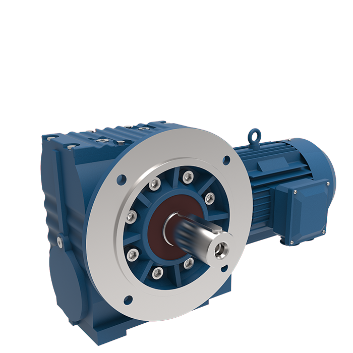
Choose a worm gear motor when your application runs intermittently, needs a large reduction in one step, or fits into a tight space. The right-angle output saves room in compact machine layouts. Many worm configurations self-lock, which holds a load without a brake. A lower upfront price also helps cost-sensitive projects. Worm units run quietly and smoothly at low RPM, and common IEC motor options make integration simple. Space-constrained machines reward the compact, right-angle form factor.
Verify output torque from the load force and drum or pulley radius, and apply a safety factor for starting loads and jams. Match motor power to the duty cycle. Check the mounting type and position, because orientation affects lubrication. Worm gearing can overheat if you size it only on torque for continuous operation, so confirm the duty cycle first. Avoid three common mistakes: choosing ratio first and ignoring torque, sizing on torque alone for continuous operation, and treating self-locking as safe holding. Add a brake where safety is critical.
Both designs fit their best applications. Match the drive to your duty cycle, space, and budget, and you get reliable performance either way.
Helical Gear Motor Applications
Matching Motor, Power, and Speed
A helical gear motor only performs well when the gearbox matches the motor's power rating and input speed. A mismatch can cause underperformance, overheating, or premature wear. Follow these steps to size the pair correctly:
Identify the motor's rated power in HP or kW, such as 15 HP. Power alone does not size the gearbox, but it anchors every later calculation.
Confirm the input speed on the motor nameplate. Common 60 Hz speeds are about 3,600 RPM for 2-pole, 1,800 RPM for 4-pole, 1,200 RPM for 6-pole, and 900 RPM for 8-pole motors.
Set the required output speed from your application. Conveyors often run 20–120 RPM, mixers 30–150 RPM, and bucket elevators 40–120 RPM.
Calculate the gear ratio as input RPM divided by output RPM. For example, 1,750 ÷ 70 = 25:1.
Calculate output torque in lb-ft as (horsepower × 5252) ÷ RPM. For a 15 HP motor at 70 RPM, that gives 1,125 lb-ft. The gearbox must be rated above your continuous output torque.
Check mounting style, shaft sizes, environmental conditions, installation space, and lubrication needs before you order.
Service Factor and Duty Cycle
Start by classifying the application as continuous or intermittent duty. Then record running hours, starts and stops, reversals, acceleration time, load inertia, ambient temperature, and any temporary overload. Set the service factor from the severity of the driven machine and your reliability target, not as a fixed shortcut. Machines with frequent loaded starts may need a different selection than units that run steadily after startup.
The service factor acts as a non-negotiable buffer against shock and under-rating for both designs. Peak torque, not average torque, drives fatigue life. Duty cycle separates the two types sharply. Worm gearboxes suit intermittent or short duty only and never fit 24/7 conveyors or winches. Parallel-shaft helical gearboxes are preferred for continuous, high-power applications, with efficiency of 98–99% per stage and excellent natural cooling through a large oil sump.
Your final choice comes down to matching the drive to your real operating conditions. Weigh duty cycle, efficiency needs, torque and load profile, ratio requirements, self-locking needs, space constraints, maintenance capacity, and total cost of ownership together. No single factor decides the answer on its own.
A helical gear motor tends to win in continuous, high-torque duty where energy savings and long service life matter most. A worm unit tends to win in intermittent duty, tight right-angle spaces, and cost-sensitive builds that need self-locking.
Still unsure which design fits your machine? Talk to our application engineers. Share your load data and duty cycle, and we will help you size the right gear motor with confidence.
FAQ
How much efficiency do you lose with a worm gear motor?
Expect roughly 40–90% efficiency from a worm unit, against 90–97% or more from a helical drive. The gap widens as ratio climbs and load rises. On a line that runs all day, that lost power shows up on every utility bill.
Does a worm gear motor really hold a load without a brake?
Many worm configurations self-lock, especially single-start units at 40:1 or higher. Treat this as a convenience, not a safety guarantee. Verify holding performance under your real load, and add an independent brake wherever unintended movement could cause injury or damage.
Why can a worm gearbox cost up to 40% less?
The simpler right-angle build and lower part count keep the purchase price down. That saving shrinks over years of running, when energy losses and wheel wear add up. Compare both units on total cost of ownership across your expected service life.
Which gear motor suits a 24/7 conveyor?
Choose a helical gear motor for continuous duty. It holds high efficiency under long running hours and runs cooler than a sliding-contact design. A worm unit fits intermittent duty better, because heat builds up during all-day operation at rated torque.
Can I get a high ratio from a helical gear motor?
Yes. Multi-stage inline builds reach very high totals. The GNORD S4 Gear Motor spans ratios from 2.8 to 10,000, so you can specify a modest single-stage unit or a multi-stage build for a very slow output.


